Home
› 3 Wire Circuit Diagram : 3 Phase Rotary Converter Wiring Diagram Download : The 14/3 cable is composed of a black, a white, a ground wire, but also an extra wire which can be red or yellow, the red being more commonly available.
3 Wire Circuit Diagram : 3 Phase Rotary Converter Wiring Diagram Download : The 14/3 cable is composed of a black, a white, a ground wire, but also an extra wire which can be red or yellow, the red being more commonly available.
3 Wire Circuit Diagram : 3 Phase Rotary Converter Wiring Diagram Download : The 14/3 cable is composed of a black, a white, a ground wire, but also an extra wire which can be red or yellow, the red being more commonly available.. This might seem intimidating, but it does not have to be. On an audio amplifier, terminal 3 would connect to the input channels. This size breaker requires a minimum of a #10 gauge wire so this wire used would be a 10/2 with ground. Wiring residential homes with 240 volts is a necessity, for powering some heating and cooling equipment as well as some large appliances. As shown in the diagram, a delta configuration requires only three wires for transmission but a wye (star) configuration may have a fourth wire.
The usb 3.0 specification is the combination of the physical superspeed bus combined in parallel with the physical usb 2.0 bus. This might seem intimidating, but it does not have to be. 3 wire rtd connections the 3 wire rtd configuration is the most commonly used rtd circuit design and can be seen in industrial process and monitoring applications. This one covers the single phase panel that uses 2 hot leads and a neutral to get 2 voltages in the same panel.this video is part of the heating and cooling. Assuming a single phase circuit with a 15 amp load on one ungrounded conductor and a 20 amp load on the other:
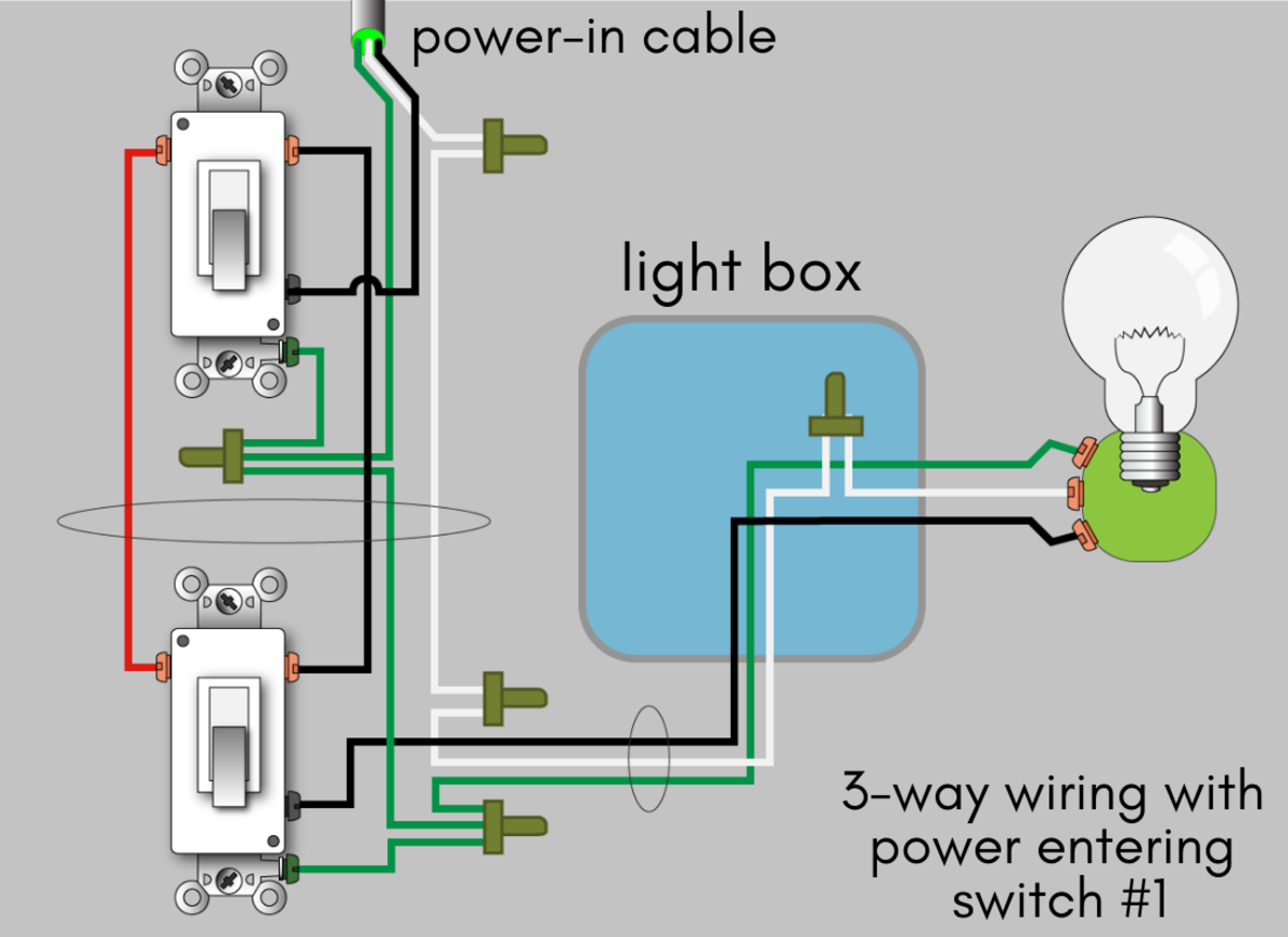
How to Wire a 3-Way Switch: Wiring Diagram | Dengarden from usercontent2.hubstatic.com The 3 prong dryer wiring diagram here shows the proper connections for both ends of the circuit. On a guitar, this would mean wiring terminal 3 to the input jack. Always use wiring diagram supplied on motor nameplate. This 3 way switch wiring diagram shows how to wire the switches and the light when the power is coming to the light switch. Solder the wire directly on to it to finish connecting the pot. With these diagrams below it will take the guess work out of wiring. Terminal 3 is where signal comes out of your pot, which means it has to be wired to the location that you want to send the signal. Transmitters are available with a wide variety of signal outputs.
This guidance note aims to outline these options.
An example is a clothes dryer. This page covers usb 3.0, refer here for usb 2.0. If the loads are on opposite phases (a correctly wired multiwire circuit), as in stubbie's very nice diagram above, you subtract the lower load from the higher to obtain the imbalance i.e. However, people still use the old 110/220 volt terms in. If you have wire strippers, simply clamp the insulated wire in the slot that matches the size of your wire, turn the strippers half a turn to score the insulation, and pull the wire through. R esponsible fo ove curr nt protection on this line) vehicle interface legend. As shown in the diagram, a delta configuration requires only three wires for transmission but a wye (star) configuration may have a fourth wire. On an audio amplifier, terminal 3 would connect to the input channels. Pick the diagram that is most like the scenario you are in and see if you can wire your switch! This size breaker requires a minimum of a #10 gauge wire so this wire used would be a 10/2 with ground. The diagram below is based on the video you watched above. The fourth wire, if present, is provided as a neutral and is normally grounded. Transmitters are available with a wide variety of signal outputs.
This size breaker requires a minimum of a #10 gauge wire so this wire used would be a 10/2 with ground. R esponsible fo ove curr nt protection on this line) vehicle interface legend. More about wiring diagrams for switches. The 4th wire in that cord and plug configuration is an equipment grounding conductor. The power can start at a fixture or either of the two switches.
3 Wire Rtd Wiring Diagram Gallery from wholefoodsonabudget.com The diagram below illustrates the control circuit needed to accomplish the operation. Terminal 3 is where signal comes out of your pot, which means it has to be wired to the location that you want to send the signal. There isn't any relationship between 3 wire cicuits being peculiar in kitchens. The 14/3 cable is composed of a black, a white, a ground wire, but also an extra wire which can be red or yellow, the red being more commonly available. An example is a clothes dryer. The power can start at a fixture or either of the two switches. The 3 prong dryer wiring diagram here shows the proper connections for both ends of the circuit. Pick the diagram that is most like the scenario you are in and see if you can wire your switch!
The implied situation aforementioned by others above, is for 2 seperate 120 volt circuits using a common neutral.
Solder the wire directly on to it to finish connecting the pot. As shown in the diagram, a delta configuration requires only three wires for transmission but a wye (star) configuration may have a fourth wire. This is a common configuration in hallways and staircases. This one covers the single phase panel that uses 2 hot leads and a neutral to get 2 voltages in the same panel.this video is part of the heating and cooling. The 14/3 cable is composed of a black, a white, a ground wire, but also an extra wire which can be red or yellow, the red being more commonly available. On a guitar, this would mean wiring terminal 3 to the input jack. R esponsible fo ove curr nt protection on this line) vehicle interface legend. The implied situation aforementioned by others above, is for 2 seperate 120 volt circuits using a common neutral. On an audio amplifier, terminal 3 would connect to the input channels. More about wiring diagrams for switches. This page covers usb 3.0, refer here for usb 2.0. The power can start at a fixture or either of the two switches. The 4th wire in that cord and plug configuration is an equipment grounding conductor.
Three wire ckts can be utilized for use in any room in a house & in most commercial applications as well. The trick is that each circuit uses a different hot wire, but they share the common wire and ground wire. 3 wire rtd connections the 3 wire rtd configuration is the most commonly used rtd circuit design and can be seen in industrial process and monitoring applications. The diagram below is based on the video you watched above. Solder the wire directly on to it to finish connecting the pot.
3-Way Switch Wiring Diagram from www.buildmyowncabin.com This might seem intimidating, but it does not have to be. Strip about 1.5 cm (5/8) of the insulation away from the end of both the black and white wires. This one covers the single phase panel that uses 2 hot leads and a neutral to get 2 voltages in the same panel.this video is part of the heating and cooling. Three wire ckts can be utilized for use in any room in a house & in most commercial applications as well. Assuming a single phase circuit with a 15 amp load on one ungrounded conductor and a 20 amp load on the other: The usb 3.0 specification is the combination of the physical superspeed bus combined in parallel with the physical usb 2.0 bus. The fourth wire, if present, is provided as a neutral and is normally grounded. However, people still use the old 110/220 volt terms in.
If the loads are on opposite phases (a correctly wired multiwire circuit), as in stubbie's very nice diagram above, you subtract the lower load from the higher to obtain the imbalance i.e.
This might seem intimidating, but it does not have to be. Transmitters are available with a wide variety of signal outputs. Three wire ckts can be utilized for use in any room in a house & in most commercial applications as well. This page covers usb 3.0, refer here for usb 2.0. The usb 3.0 specification is the combination of the physical superspeed bus combined in parallel with the physical usb 2.0 bus. Wiring diagram book a1 15 b1 b2 16 18 b3 a2 b1 b3 15 supply voltage 16 18 l m h 2 levels b2 l1 f u 1 460 v f u 2 l2 l3 gnd h1 h3 h2 h4 f u 3 x1a f u 4 f u 5 x2a r. Always use wiring diagram supplied on motor nameplate. On an audio amplifier, terminal 3 would connect to the input channels. Pick the diagram that is most like the scenario you are in and see if you can wire your switch! Solder the wire directly on to it to finish connecting the pot. If we draw a circuit showing each voltage source to be a coil of wire (alternator or transformer winding) and do some slight rearranging, the y configuration becomes more obvious in figure below. Assuming a single phase circuit with a 15 amp load on one ungrounded conductor and a 20 amp load on the other: This control circuit is a variation of the three wire control circuit.