Home
› 7 Way Trailer Wiring Diagram : 7 Way Trailer Wiring Diagram With Battery 36guide Ikusei Net / A wiring diagram is a streamlined standard pictorial depiction of an electrical circuit.
7 Way Trailer Wiring Diagram : 7 Way Trailer Wiring Diagram With Battery 36guide Ikusei Net / A wiring diagram is a streamlined standard pictorial depiction of an electrical circuit.
7 Way Trailer Wiring Diagram : 7 Way Trailer Wiring Diagram With Battery 36guide Ikusei Net / A wiring diagram is a streamlined standard pictorial depiction of an electrical circuit.. A fundamental toolkit can also be valuable in fixing unforeseen technicalities. It shows the components of the circuit as simplified shapes, and the capacity and signal connections with the devices. Variety of dodge trailer wiring diagram 7 pin. This curt 7 pin trailer wiring diagram version is more appropriate for sophisticated trailers and rvs. As a professional rv transporter i have seen to many trucks wired with those 2 wires to small and cause a fire from overheating.
4 way flat molded connectors allow basic hookup for three lighting functions; A very first look at a circuit layout could be complicated, yet if you can check out a subway map, you could check out schematics. Variety of phillips 7 way trailer plug wiring diagram. 7 way trailer wiring diagram ford f250 Trying to map the colors but the descriptions used by featherlite are if your trailer has the same wire colors as the diagram you attached the blue wires would.
7 Way Rv Plug Wiring Irv2 Forums from www.irv2.com Keep current on featherlite's innovative new trailers at wiringall.com the part of the tire that is made of steel wires, wrapped or reinforced by ply. Each component ought to be set and connected with different parts in particular manner. Australian trailer plug and socket wiring diagrams. 12 pin flat this is an extension of the 7 pin flat. It shows the components of the circuit as simplified shapes, and the capacity and signal connections with the devices. 7 pin flat the best! Next, connect the corresponding wires to the equivalent ports on the left side of the guiding column. A fundamental toolkit can also be valuable in fixing unforeseen technicalities.
Right turn signal / stop light (green), left turn signal / stop light (yellow), taillight / license / side marker (brown) and a ground (white).
It reveals the parts of the circuit as streamlined forms, and the power and also signal links between the tools. Trailer wiring diagrams trailer wiring connectors various connectors are available from four to seven pins that allow for the transfer of power for the lighting as well as auxiliary functions such as an electric trailer brake controller, backup lights, or a 12v power supply for a winch or interior trailer lights. By law, trailer lighting must be connected into the tow vehicle's wiring system to provide trailer running lights, turn signals and brake lights. Each component ought to be set and connected with different parts in particular manner. A fundamental toolkit can also be valuable in fixing unforeseen technicalities. It shows the components of the circuit as simplified shapes, and the capacity and signal connections with the devices. For a single axle, 14 gage is good, but for tandem axles, use 12 gage wire. 4 way flat molded connectors allow basic hookup for three lighting functions; A duplicate of your wiring diagram on your camper may possibly are available in helpful, in addition to a circuit tester, a set of linesman pliers, some electrical wire, tape, and connectors. The safety of all individuals on or off the roadway, as well as those operating a motorized vehicle, depends upon understanding how to run the system. Getting from point a to point b. Trailer wiring diagrams 4 way systems. Next, connect the corresponding wires to the equivalent ports on the left side of the guiding column.
Literally, a circuit is the course that enables power to flow. Australian trailer plug and socket wiring diagrams; When wiring a trailer connector, it is best to wire by function, as wire colors can vary. Need to know which color wire go to which post. It shows the components of the circuit as simplified shapes, and the capacity and signal connections with the devices.
Chevy Trailer Wiring Harness Diagram Wiring Diagram Scrape from static-assets.imageservice.cloud When issues happen with the trailer, driver might wish to learn where the problem spot can be located. In the trailer wiring diagram and connector application chart below, use the first 5 pins,. Australian trailer plug and socket wiring diagrams; Variety of phillips 7 way trailer plug wiring diagram. A wiring diagram is a simplified standard photographic depiction of an electric circuit. Variety of dodge trailer wiring diagram 7 pin. Literally, a circuit is the course that enables power to flow. Next, connect the corresponding wires to the equivalent ports on the left side of the guiding column.
A duplicate of your wiring diagram on your camper may possibly are available in helpful, in addition to a circuit tester, a set of linesman pliers, some electrical wire, tape, and connectors.
A very first look at a circuit layout could be complicated, yet if you can check out a subway map, you could check out schematics. As a professional rv transporter i have seen to many trucks wired with those 2 wires to small and cause a fire from overheating. Trailer wiring diagrams trailer wiring connectors various connectors are available from four to seven pins that allow for the transfer of power for the lighting as well as auxiliary functions such as an electric trailer brake controller, backup lights, or a 12v power supply for a winch or interior trailer lights. This curt 7 pin trailer wiring diagram version is more appropriate for sophisticated trailers and rvs. 12 pin flat this is an extension of the 7 pin flat. Trying to map the colors but the descriptions used by featherlite are if your trailer has the same wire colors as the diagram you attached the blue wires would. 7 pin flat the best! It reveals the parts of the circuit as streamlined forms, and the power and also signal links between the tools. Getting from point a to point b. By law, trailer lighting must be connected into the tow vehicle's wiring system to provide trailer running lights, turn signals and brake lights. Don't skimp on wire size for your brakes. Trailer wiring diagrams 4 way systems. It shows the components of the circuit as simplified shapes, and the capacity and signal connections with the devices.
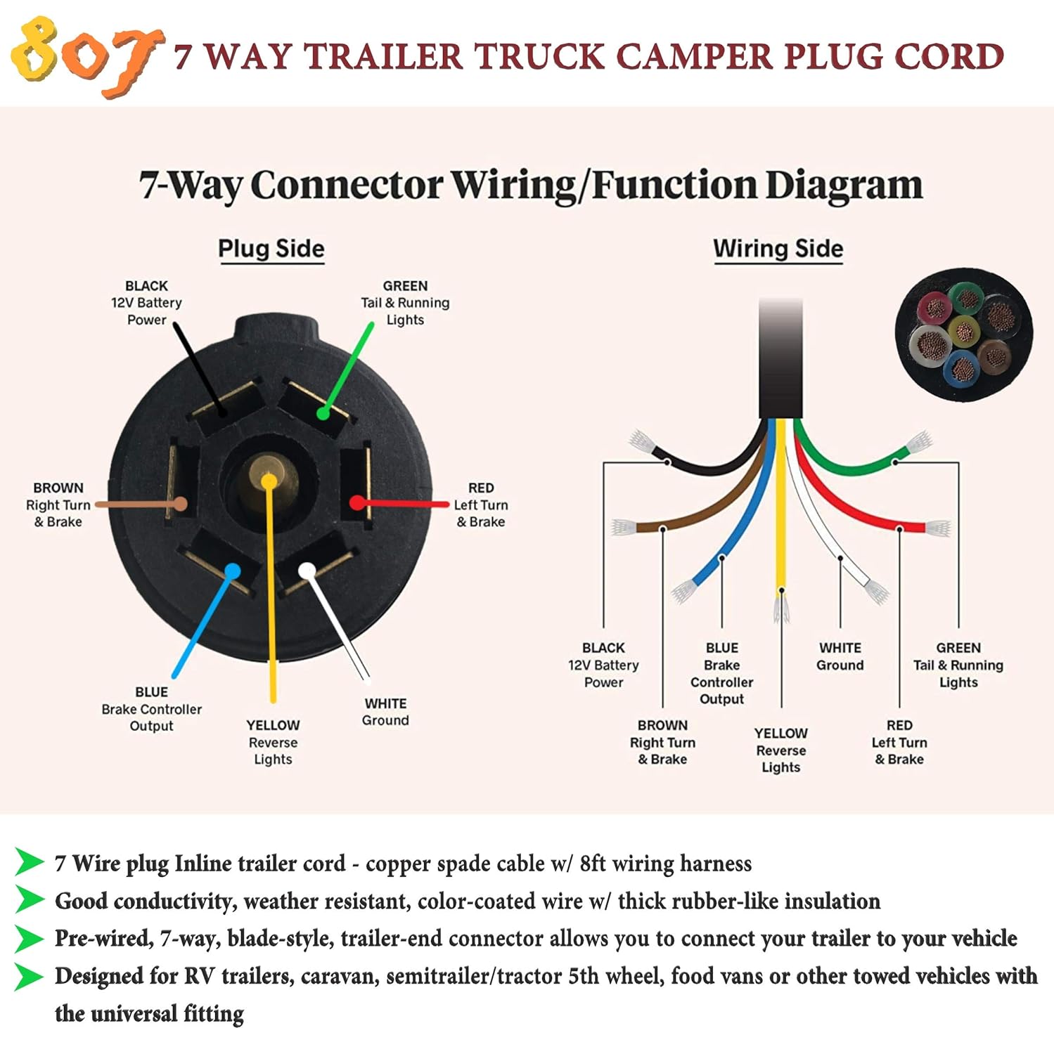
We have an excellent wiring diagram on our website, i will provide you a link so you. It shows the components of the circuit as simplified shapes, and the capacity and signal connections with the devices. 7 way plug wiring diagram standard wiring* post purpose wire color tm park light green (+) battery feed black rt right turn/brake light brown lt left turn/brake light red s trailer electric brakes blue gd ground white a accessory yellow this is the most common (standard) wiring scheme for rv plugs and the one used by major auto manufacturers today. By law, trailer lighting must be connected into the tow vehicle's wiring system to provide trailer running lights, turn signals and brake lights. The safety of all individuals on or off the roadway, as well as those operating a motorized vehicle, depends upon understanding how to run the system.
Diagram Side Plug Truck Wiring Diagram 7 Full Version Hd Quality Diagram 7 Widewebdiagram Aifipuglia It from images-na.ssl-images-amazon.com Australian trailer plug and socket wiring diagrams; For a single axle, 14 gage is good, but for tandem axles, use 12 gage wire. Trailer wiring diagrams 4 way systems. 4 way flat molded connectors allow basic hookup for three lighting functions; Trying to map the colors but the descriptions used by featherlite are if your trailer has the same wire colors as the diagram you attached the blue wires would. 7 way trailer wiring diagram is explained in details in the picture and the table below: Getting from point a to point b. Standard dot wiring sealed wiring harness right turn ground left turn running lights 12v + brakes auxiliary (not used) yellow white green brown wire brown) 7 way rv (blade) plug trailer side c34/wedge w/ sealed wiring harness yellow white green yellow white white green green brown yellow white green yellow white green brown red
When issues happen with the trailer, driver might wish to learn where the problem spot can be located.
7 pin flat the best! A very first look at a circuit layout could be complicated, yet if you can check out a subway map, you could check out schematics. The purpose is the very same: 7 way plug wiring diagram standard wiring* post purpose wire color tm park light green (+) battery feed black rt right turn/brake light brown lt left turn/brake light red s trailer electric brakes blue gd ground white a accessory yellow this is the most common (standard) wiring scheme for rv plugs and the one used by major auto manufacturers today. Trailer electrical connectors come in a variety of shapes and sizes. A wiring diagram is a simplified standard photographic depiction of an electric circuit. If your vehicle is not equipped with a working trailer wiring harness, there are a number of different solutions to provide the perfect fit for. 7 way trailer wiring diagram is explained in details in the picture and the table below: Right turn signal / stop light (green), left turn signal / stop light (yellow), taillight / license / side marker (brown) and a ground (white). Standard dot wiring sealed wiring harness right turn ground left turn running lights 12v + brakes auxiliary (not used) yellow white green brown wire brown) 7 way rv (blade) plug trailer side c34/wedge w/ sealed wiring harness yellow white green yellow white white green green brown yellow white green yellow white green brown red A duplicate of your wiring diagram on your camper may possibly are available in helpful, in addition to a circuit tester, a set of linesman pliers, some electrical wire, tape, and connectors. Australian trailer plug and socket wiring diagrams; As a professional rv transporter i have seen to many trucks wired with those 2 wires to small and cause a fire from overheating.