How To Read Diagrams : Lecture 05 / It goes exactly the same for the other switches that we have here as well.. An oscilloscope generates an eye diagram by overlaying sweeps of different segments of a long data stream driven by a master clock. This is what we draw using autocad electrical. It goes exactly the same for the other switches that we have here as well. First two chapters are devoted to philosophy of reading schematics and block diagrams. A resistor the symbol for a resistor how do you read circuits diagrams?
In addition to the symbols, every component on electrical schematics has a unique name and value, which further helps to identify what it represents.component names are usually a combination of one or two letters and sometimes a number. Recognizing circuit diagrams symbols once you know the language or terms of circuit diagrams, you are half way of being able to reading them. The power supply is shown at the top and the earth at the bottom to facilitate understanding of the current flow. Knowing how to read circuits is a very useful skill that will help you out all the time. The adage a picture is worth a thousand words applies when it comes diagrams and charts.
Draw timing diagram of memory read and memory write machine cycle in maximum mode and explain it. from i.imgur.com Diagrams and charts are important because they present information visually. The symbols are an abstract drawing of the original component and are kept standard for anyone to understand. Refer to the figure, an electrical wiring diagram is surrounded by the rectangular box. I have to admit, that these chapters have been the most beneficial for me. Because the diagrams are printed in color, identifying the wires shown on the wiring diagram in the vehicle harness or at the connectors is a lot easier. Edraw provides all kinds of symbols required in piping and instrumentation diagrams. But sometimes, designers make some exceptions to have a better layout such as this page. Look for circles filled with symbols that signify the power source.
This is the natural flow, and it's the best way to read them.
The first step to read a piping and instrumentation diagram is to know how to read its symbols and shapes in the drawing. A drawing of an electrical or electronic circuit is known as a circuit diagram, but can also be called a schematic diagram, or just schematic. The symbols are an abstract drawing of the original component and are kept standard for anyone to understand. The composition for each of these points is shown below. Shared control/display, computer, function, and programmable logic. Because the diagrams are printed in color, identifying the wires shown on the wiring diagram in the vehicle harness or at the connectors is a lot easier. The adage a picture is worth a thousand words applies when it comes diagrams and charts. We begin with a basics fuel pump & relay diagram See their number is in the horizontal axis and alphabets in the vertical axis. System circuit diagrams the entire ewd is built around the system circuit diagram. Don't skip over diagrams and graphs when reading! The diagram below is a basic car light circuit, at first sight it might look complicated, but as you understand the flow, it will become clear. This instructable will show you exactly how to read all those confusing circuit diagrams and then how to assemble the circuits on a breadboard!
Refer to the example on page 3 for the basic layout of the wiring diagram. How to read ac or air conditioner condenser unit wiring diagram / schematic. Breadboards are a great way to make temporary, functional, prototype circuits. Select a subsystem or component (if required). Knowing how to read circuits is a very useful skill that will help you out all the time.
How to Read a Schematic - learn.sparkfun.com from cdn.sparkfun.com So to sum it all up, here is what we learned in this article: I have to admit, that these chapters have been the most beneficial for me. Also observe that the ternary diagram is read counter clockwise. I go over 4 ac condenser wiring diagrams and explain how to read them and what a. Note that standard power sources are labeled with a circle that's filled with a plus or minus sign, while an ideal source looks like a circle with a horizontal line splitting it in half. Because the diagrams are printed in color, identifying the wires shown on the wiring diagram in the vehicle harness or at the connectors is a lot easier. Each electronic component has a symbol. See their number is in the horizontal axis and alphabets in the vertical axis.
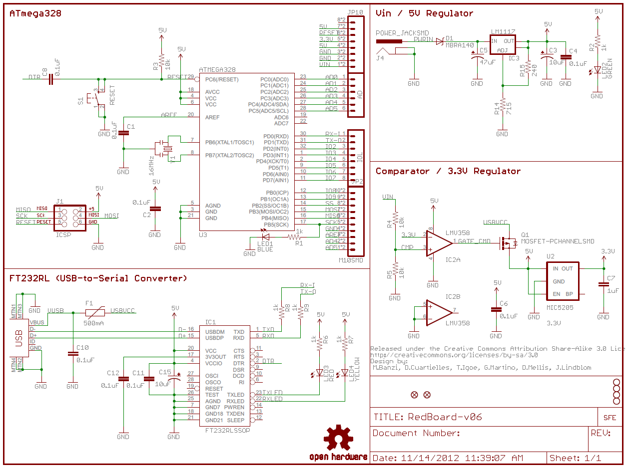
A circuit diagram, or a schematic diagram, is a technical drawing of how to connect electronic components to get a certain function.
Central/relay panel the central/relay panel is indicated in gray at the top of the wiring diagram page. There are several lines and a lot of symbols all over the page. Knowing how to read circuits is a very useful skill that will help you out all the time. We begin with a basics fuel pump & relay diagram Www.handymanpf.complease help support this channel via paypal so i can continue to improve and make quality videos and make product reviews to help save you. Diagrams and charts are important because they present information visually. Conductor symbols crossing where they do not connect is kept to a minimum. Nearly all modern diagrams are laid out with the power at the top of the page/screen and the ground at the bottom. How to read ac or air conditioner condenser unit wiring diagram / schematic. System circuit diagrams the entire ewd is built around the system circuit diagram. Breadboards are a great way to make temporary, functional, prototype circuits. The symbols are an abstract drawing of the original component and are kept standard for anyone to understand. Look for circles filled with symbols that signify the power source.
We begin with a basics fuel pump & relay diagram Recognizing circuit diagrams symbols once you know the language or terms of circuit diagrams, you are half way of being able to reading them. Each electronic component has a symbol. The adage a picture is worth a thousand words applies when it comes diagrams and charts. Knowing how to cut, strip, and connect wire is an important electronics skill.
Learn How to Read P&ID Drawings - A Complete Guide from i0.wp.com Scan over your schematics to figure out where your electrical currents are generated. Often when working on appliances, it is necessary to read these diagrams when there is an electrical problem with the appliance you are working on. How to read ac or air conditioner condenser unit wiring diagram / schematic. I have to admit, that these chapters have been the most beneficial for me. This is the natural flow, and it's the best way to read them. An oscilloscope generates an eye diagram by overlaying sweeps of different segments of a long data stream driven by a master clock. Especially if you start messing around with building little electronics projects. Www.handymanpf.complease help support this channel via paypal so i can continue to improve and make quality videos and make product reviews to help save you.
Here is an overview of the most used symbols in circuit diagrams.
Names can be associated with zero or exactly one address; The power supply is shown at the top and the earth at the bottom to facilitate understanding of the current flow. Note that the heavy red lines are not included in this final triangle. See their number is in the horizontal axis and alphabets in the vertical axis. After seeing a few circuit diagrams, you'll quickly learn how to distinguish the different symbols. Knowing how to read a wiring diagram can save you from buying parts you don't need. Don't skip over diagrams and graphs when reading! Note that standard power sources are labeled with a circle that's filled with a plus or minus sign, while an ideal source looks like a circle with a horizontal line splitting it in half. Scan over your schematics to figure out where your electrical currents are generated. Breadboards are a great way to make temporary, functional, prototype circuits. Nearly all modern diagrams are laid out with the power at the top of the page/screen and the ground at the bottom. Select a diagram to display it and any associated diagrams. Learn to read electrical and electronic circuit diagrams or schematics.